

𝗦𝗵𝗼𝗿𝘁 𝗮𝗻𝘀𝘄𝗲𝗿. Battery performance depends on what forms at electrode–electrolyte and solid–solid interfaces, where it forms, and how it changes with cycling. PHI combines inert sample transfer, cryogenic handling, XPS, Auger electron spectroscopy (AES), and time-of-flight secondary ion mass spectrometry (TOF-SIMS) to preserve sensitive materials and connect chemical states, nanoscale features, and depth distributions. The methods help researchers distinguish real degradation from changes caused by transfer or analysis.
Key takeaways
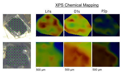
- XPS mosaics showed that a coated, cycled cathode had a more uniform chemical distribution and less F–Li associated with side reactions than an uncoated cathode.
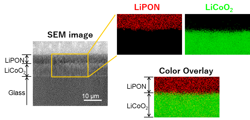
- AES distinguished lithium chemical states at a LiPON/LiCoO₂ boundary after the study optimized conditions to limit electron-beam damage.
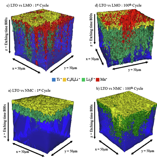
- TOF-SIMS depth profiles revealed Mn-related signals at the LTO electrode facing LMO, along with different distributions of organic and inorganic SEI species.
Which problem are you trying to solve?
| Battery question | Measurement | Information gained |
|---|---|---|
| Is the cathode–electrolyte interphase uniform after cycling? | Scanning XPS microprobe, SXI navigation and spectral mosaics | Where LiF and other chemical states accumulate across an electrode |
| Where does lithium chemistry change at a solid electrolyte–cathode boundary? | Scanning AES on a prepared cross-section | Spatial distribution of lithium chemical states at a small interface |
| Which reaction products or migrating species are present at the surface and below it? | TOF-SIMS imaging and depth profiling | Molecular fragments, trace species and their lateral and depth distributions |
XPS identifies and maps chemical bonding states as battery materials change during operation. AES resolves chemistry on smaller features. TOF-SIMS detects diagnostic ions and molecular fragments with trace-level sensitivity. Comparing results can add context, but a SIMS fragment alone is not a unique molecular identification. Reference spectra and complementary XPS help test assignments.
Preserve the interface before measuring it
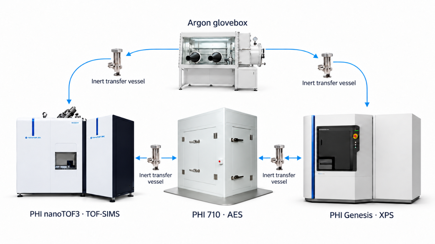
Many lithium-containing electrodes and interphases react with air, changing their composition before analysis. PHI transfer vessels carry samples between a glovebox and compatible XPS, AES and TOF-SIMS instruments without deliberate ambient exposure. They also allow samples to return to an inert environment for further analysis.
Cryogenic handling addresses changes during measurement. In a lithium-metal SEI comparison, cryogenic XPS retained chemistry that evolved during room-temperature vacuum analysis, including differences in LiF and Li₂O. A separate PEO-LiTFSI solid-electrolyte study found that cooling during XPS reduced X-ray-induced decomposition to LiF. The two studies address different materials and sources of change.
Examples from battery research
Is a cathode coating changing where interphase products form?
Scanning X-ray induced secondary electron images (SXI) located features on cycled cathodes, while XPS spectral mosaics mapped elemental and F 1s chemical-state distributions. After cycling, the coated cathode had a more uniform distribution and less of the F–Li component associated with side reactions than the uncoated cathode. The samples were disassembled in a glovebox and transferred under inert conditions. These measurements show where chemistry differs across the electrode, which a single average spectrum can miss.
Read the coated-cathode analysis overview →
Where does lithium chemistry change at a solid–solid boundary?
At a LiPON/LiCoO₂ cross-section, AES distinguished the spatial distributions of lithium in the electrolyte and cathode. The study optimized electron energy, dose, current and sample temperature because LiPON is beam sensitive. The resulting maps add local chemical evidence to questions raised by electrochemical measurements.
Read the LiPON/LiCoO₂ AES example →
Do reaction products or migrating metals extend into the SEI?
TOF-SIMS imaging and depth profiling compared LTO electrodes cycled against LMO and NMC cathodes. Mn-related signal was found at the LTO electrode facing LMO. Organic species were concentrated at the top of the SEI, while LiF and Mn-related signals extended deeper. These distributions help researchers investigate transition-metal migration and differences between the two cell systems.
Read the LTO/LMO and LTO/NMC study →
How to choose your technique
Start with the size and location of the feature, then decide whether you need chemical states, local elemental chemistry or ion distributions with depth.
| Method | Best fit | Check before testing |
|---|---|---|
| Scanning XPS | Chemical states across a heterogeneous electrode surface | Whether the selected analysis area averages over different features |
| AES | Local chemistry across a small solid–solid boundary | Electron-beam dose and charging on sensitive materials |
| TOF-SIMS | Trace secondary ions and their lateral and depth distributions | Reference-based ion assignment and possible changes during profiling |
Build a repeatable battery analysis workflow
- Define the failure question. Record cell chemistry, cycle state, sampling location and the comparison to be made.
- Control handling. Disassemble and mount in a suitable inert environment. Use inert transfer and cryogenic conditions when the chemistry requires them.
- Locate the feature. Use SXI on XPS, SEM on AES or ion imaging on TOF-SIMS. Prepare a cross-section when the solid–solid boundary is the target.
- Measure complementary evidence. Map XPS chemical states, AES local lithium chemistry and TOF-SIMS ion distributions on matched samples or locations where practical. Use a compatible transfer vessel between systems when air exposure matters.
- Check for artifacts. Set charge compensation for insulating specimens as needed. Compare beam dose, temperature and profile conditions against controls. Choose an appropriate cluster-ion sputter source for organic-rich layers and verify that sputtering has not changed the chemical assignment.
- Standardize the record. Save acquisition settings, charge referencing, transfer history, locations, depth calibration and analysis rules so multiple users can compare results.
Cluster-ion profiling can reduce damage for some organic-rich materials, but no sputter recipe is universally nondestructive. Charge compensation and energy referencing require validation for each material.
Frequently asked questions
Why combine XPS and TOF-SIMS for a battery interface?
XPS measures elemental composition and chemical states. TOF-SIMS adds sensitive ion and molecular-fragment maps and depth distributions. Comparing them can strengthen assignments of interphase products and distinguish a surface reaction from a deeper migration pathway.
When is cryogenic XPS useful?
Use it when volatile or reactive interphases change during room-temperature vacuum analysis, or when cooling reduces measurement-induced decomposition. Record the temperature history from preparation through analysis and compare with room-temperature controls when appropriate.
Can depth profiling show the original interphase without changing it?
Cluster-ion sputtering can limit damage in some organic-rich layers, but it can still mix layers or alter chemistry. Compare profiles with the unprofiled surface. Cr Kα HAXPES can provide a deeper, non-sputtered reference when the interface signal is accessible through the overlayer.
Tell us the electrode chemistry, cycle state and interface question. We can define handling and measurements across XPS, AES and TOF-SIMS.
Contact PHI Contact PHI